- Pressure Sensor, Pressure Transducer, Pressure Transmitter

- 2020-08-21
- Zhyq
- 29
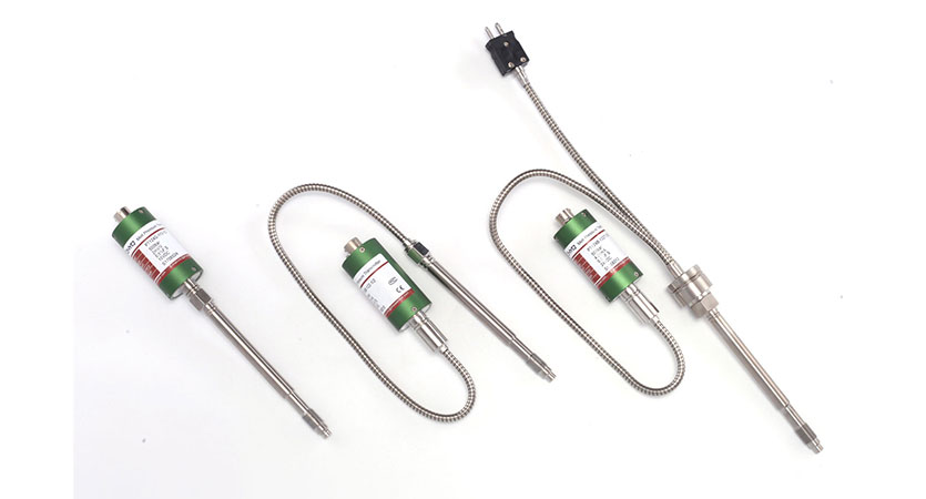
Take Good Care of Your Extrusion Pressure Transducers
Melt pressure transducers are used to improve extruder output and melt quality, improve production safety, and protect your machinery. Meeting product quality specifications such as part dimensions and surface finish with minimal material waste requires maintaining optimum processing pressure during production.
Transducers are sensitive components that are easily damaged if not installed and maintained correctly. Following a few simple guidelines will help ensure the longevity of your sensors and enable you to get accurate, reliable measurements.
Why sense melt pressure?
Melt-pressure instrumentation on an extruder can range from a single transducer measuring one pressure point to a series of transducers measuring the entire process and tied to instrumentation that will record data, sound an alarm, give warnings to take corrective actions, and relay information to a process-control system.
Stable output with reduced scrap and material waste is maintained by pressure transducers at the die entrance in conjunction with a pressure control device. Pressure measurements across a screen pack and melt pump are also important for safety and optimum performance.
A melt transducer downstream of the screen pack will alert operators if flow to the die is restricted, while one upstream of the screen pack will warn of a high-pressure situation that may produce excessive wear to the screw’s thrust bearing. For processors using melt pumps, measuring both inlet and outlet pressures ensures constant melt flow at the die and signals any restriction in melt flow that could damage the pump.
Tip #1: Mount them correctly
Damage to a pressure transducer is commonly caused by its installation in an improperly machined hole. In forcing a transducer into a too-small or eccentric hole, the transducer diaphragm may be crushed and the instrument will not function.
Tool kits available for machining the mounting hole will help to make sure the holes are properly sized. A mounting torque of 100 to 200 in.-lb (for 1/2-20 UNF threads) is essential to form an adequate seal, but excessive mounting torque will cause seizing. To prevent seizing, apply a high-temperature anti-seize compound to the transducer threads prior to installation. Transducers installed at a mounting torque above 500 in.-lb will be difficult to remove even when anti-seize compound is applied.
Tip #2: Check hole thread size
Abrasion from screwing a transducer into a mounting hole with an incorrect thread size will damage the instrument’s threads. This may prevent a tight seal, resulting in melt leakage, and the instrument will not function properly or safely. Correct dimensions for the mounting hole must be used to avoid thread galling. (The threads are generally the industry standard of 1/2-20 UNF 2B.) A mounting-well gauge plug should be used to verify that the mounting hole is correctly machined and cleaned.
Tip #3: Keep mounting holes clean
It is important to keep transducer mounting holes clean and free of any plastic build-up. Before an extruder is cleaned, all of the transducers should be removed from the barrel to avoid their being damaged. When they are removed, plastic is likely to flow into the mounting holes and harden. If this plastic residue is not removed, extensive sensor tip damage will result when the transducers are re-inserted.
A cleaning tool kit can be used to remove the plastic contamination. But note that repeated cleaning may produce “too deep” holes and result in damage to the transducer tip. If this occurs, spacers should be used to raise the transducer.
Leave Your Inquiry
Your email address will not be published. Required fields are marked *