- Pressure Sensor, Pressure Transducer, Pressure Transmitter

- 2023-05-30
- Zhyq
- 137
Unctions and Calibration Information for Differential Pressure Transmitter
A: How to distinguish positive and negative pressure in differential pressure transmitter?
- DifferentWorking Principle:
- When testing positive pressure, positive chamber needs to connect to measuring source. Negative chamber will be open to ambient air pressure.
- When testing negative pressure, we need to connect negative chamber to measuring source. Positive chamber will be open to ambient air pressure.
- Different Voltage
- Thereare three volves installed in differential pressure transmitters – high pressure volve, low pressure volve and balance volve. Balance volve need to be open to make sure differential pressure transmitter works perfectly.
- Differentrole
- Three valves manifold is normally structured with pressure transmitter as a combined set up. The three valves manifold can separate positive and negative pressure measuring chamber and the priming point. It can also open and close the connection between three of them. The main purpose to set up this way is using as a balance valve during installation and demolition process. Hence to avoid damage to the transmitter if overload capacity is not strong enough.
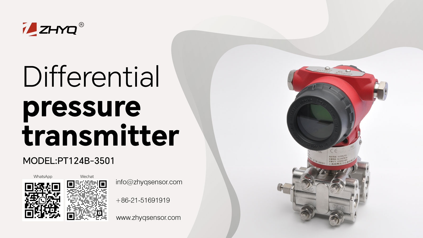
B: Main structure of differential pressure transmitter
- Direct pressure sensing element are located at the lower chamber of differential pressure transmitter. Most types of differential pressure transmitters are equipped with diaphragms as pressure sensing element. It is a mechanical device and located between two of the pressure inlets. The diaphragm will deflect by applying pressure and then convert pressure into an electronic signal. This process is normally done by sensors. Commonly used sensors are strain gauge, differential capacitors and vibration strings. Output from sensors is proportional to the pressure applied.
- Electronic unit as the other important part of differential pressure transmitter is located at the upper chamber. The electrical signal generated by the sensor in the lower chamber is in the millivolt range. The signal will be amplified to the 0-5V or 0-10V range, or converted to 4-20mA for forward transmission to remote instruments.
C: Calibration
When differential pressure input set at zero, output will be shown at 4mA as the lowest signal output. Output will be shown at 20mA when differential pressure input is set at the maximum pressure range. Low, medium and high voltage capacitive differential pressure transmitters have an accuracy of 0.2%FS, including linear, variable and vertical errors. The linear error is ±0.1% of the calibration range, the variation is ±0.5% of the calibration range, and the repeatability error is ±0.5% of the calibration range. Zero drift will be carried out when accuracy is adjusted. Insert the connector SW1 in the appropriate position according to positive or negative migration. Then add the zero-drift signal to the transmitter, adjust the zero-adjustment screw, so that the output current of the transmitter is 4mA, then the zero-drift adjustment is completed. Repeatedly adjust the zero and address until they meet the accuracy requirements. It can be slightly adjusted when necessary.
D: Installation Hints:
- Check whether the valves, pressure guide pipes and live joints are firmly connected;
- Check whether the secondary valve and blowdown valve are closed and the balance valve is open;
- Open the valve slightly, and then check the pressure guide pipe, valve, loose joint, etc. If there is no leakage, open all valves at once;
- Open the drainage valve respectively and close it afterthe draining process;
- Loosen the differential pressure chamber and remove air;
- Differential pressure transmitter can only be started when the pressure guide tube is filled with condensate water;
- Start the differential pressure transmitter in the order of positive pressure valve, balance valve and negative pressure valve
Leave Your Inquiry
Your email address will not be published. Required fields are marked *